Multiplexer

Multiplexers (MUX)
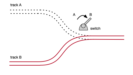
A common combinational circuit is the multiplexer. A multiplexer (“MUX” for short) is a multi-channel switch that selects an input based on a control input and sends this to the output. Here’s an analogy: Think of a railroad track where you have two separate tracks merge into one. You’d need to route trains through one at a time (or disaster would ensue). Someone (or some thing) would have to pull a lever to route trains from one track or the other onto the merged track.
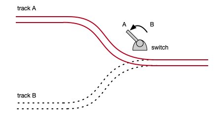
Train traffic can flow on only one of these tracks at the same time. Throw the switch and now traffic flows on the other track.
A MUX is just an electronic device, built using gates, that performs the same function—choosing from one of multiple inputs, and directing that to the output. A MUX’s control input is like the lever that switches the track. With a device like this, we can, based on some condition or conditions, choose among the inputs and switch electronically.
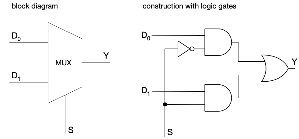
The simplest MUX is like the train track shown: a 2-to-1 multiplexer. A 2-to-1 multiplexer has two data inputs (conventionally labeled, D_0 and D_1), one control input (S), and one output (Y). If the control input is 0, D_0 is routed to output. If the control input is 1, D_1 is routed to output.
In Boolean form: Y = (\neg S \land D_0) \lor (S \land D_1).
The MUX is built from an inverter (to get \neg S), two AND gates (to combine each data input with the correct select signal), and one OR gate (to combine the results).
Multiplexers can operate on both single-bit signals as well as multi-bit buses such as D_0 = \texttt{1010}_2, D_1 = \texttt{1100}_2 making them very useful for real CPUs that use a 32- or 64-bit architecture.
We can make a truth table for a 2-to-1 MUX, but we’ll need some way to indicate that one data line is switched off and its values cannot affect output (this being the purpose of a MUX—to select only one of multiple inputs to be directed to output). Here we’ll use ‘·’ to indicate that the input does not affect the output when the select line chooses a different input). With that in mind, here’s the truth table for a 2-to-1 multiplexer.
| S | D_0 | D_1 | Y |
|---|---|---|---|
| 0 | 0 | · | 0 |
| 0 | 1 | · | 1 |
| 1 | · | 0 | 0 |
| 1 | · | 1 | 1 |
So if the control input (S) is 0, D_0 is chosen, and the output (Y) is whatever appears on the D_0 line. If the control input is 1, then D_1 is chosen, and the output is whatever appears on the D_1 line.
Here’s a block diagram and construction with logic gates:
Multiplexers often have more than two data inputs. Here is a 4-to-1 multiplexer, which has four data inputs, (D_0, D_1, D_2, and D_3), and two select lines, (S_1 and S_0). Regardless of the number of inputs, the MUX still produces one output.
Here is the Boolean equivalent: Y = (\neg S_1 \land \neg S_0 \land D_0) \lor (\neg S_1 \land S_0 \land D_1) \lor (S_1 \land \neg S_0 \land D_2) \lor (S_1 \land S_0 \land D_3).
The truth table for a 4-to-1 multiplexer is
| S_1 | S_0 | D_0 | D_1 | D_2 | D_3 | Y |
|---|---|---|---|---|---|---|
| 0 | 0 | 0 | · | · | · | 0 |
| 0 | 0 | 1 | · | · | · | 1 |
| 0 | 1 | · | 0 | · | · | 0 |
| 0 | 1 | · | 1 | · | · | 1 |
| 1 | 0 | · | · | 0 | · | 0 |
| 1 | 0 | · | · | 1 | · | 1 |
| 1 | 1 | · | · | · | 0 | 0 |
| 1 | 1 | · | · | · | 1 | 1 |
An n-to-1 multiplexer requires \log_2(n) select lines.
The general Boolean expression for an n-way multiplexer is:
Y = \bigvee_{i=0}^{n-1} \Big( D_i \;\land\; \bigwedge_{j=0}^{k-1} t_{ij} \Big).
where each t_{ij} is either S_j or \neg S_j, depending on the j-th bit of the binary representation of i.
Now, you might be thinking, how is the control input decided? Referring back to our train example, what makes the operator switch the track, what are the conditions? The control inputs of a MUX are signals coming from other parts of the larger connected circuit, more often than not from the control unit of the CPU.
Think back to the fetch-decode-execute cycle. The control unit determines what operation needs to happen based on the instruction: is this addition? is this multiplication? is this a branch, etc. These are then turned into control signals which goes into these combinational circuits. Based on these control signals, we select a certain input data.
Example
In the CPU, after each instruction the program counter (PC) is updated. Depending on the instruction, a different operation occurs. If it is a normal instruction then the next PC should be four more than the current PC (assuming fixed 32-bit instructions) but if it’s a branch instruction, the next PC should be a completely different address representing the branch target. These become the two data inputs:
- If the instruction is not a branch, then the control unit sets S = 0, causing the MUX to output D_0 = \text{PC} + 4.
- If the instruction is a branch, the control unit sets S = 1, causing the MUX to output D_1 = \text{branch target}. This is an example of a selection circuit—the select line(s) control which input is sent to the output based on some condition.
© 2025 Clayton Cafiero.
No generative AI was used in writing this material. This was written the old-fashioned way.