Logic Gates

What exactly are logic gates and how do they help drive the decision-making process in circuits? Logic gates are the physical representation of Boolean expressions, which we know, evaluate to true or false (1 or 0). These gates take signals representing 0 or 1 (with 0 being a low voltage and 1 a high voltage), and perform some Boolean operation, with the result at the output of the gate.
There are many different types of logic gate, including:
- NOT,
- AND,
- OR,
- NOT,
- NAND (NOT AND),
- NOR (NOT OR),
- XOR (exclusive OR), and
- XNOR (exclusive NOR, referred to as the equivalence gate).
Some of these should be familiar, especially if you’ve taken some sort of logic course but some of them may be new.
NOT, AND, and OR
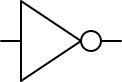
NOT gate
The NOT gate is essentially a negation. If the input is 1 then the output is 0. In Boolean algebra, this is written as Y = \neg P.
There’s a symbol we use for this gate when we’re drawing logic circuits. It looks like this:
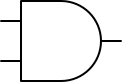
AND gate
The AND gate produces an output of 1 if and only if both of its inputs are 1. In Boolean algebra this is written as Y = P \land Q.
Here’s the symbol for an AND gate, with the two inputs on the left and the output on the right:
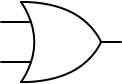
OR Gate
The OR gate produces an output of 1 if at least one of its inputs are 1. In Boolean algebra, this is written as Y = P \lor Q.
Here’s the symbol for an OR gate, with the two inputs on the left and the output on the right:
Truth tables
Each of these gates can be represented with a truth table, which lists all possible input combinations and their resulting output. Truth tables are a straightforward way to describe a gate’s behavior mathematically.
| P | NOT (\neg P) |
|---|---|
| 0 | 1 |
| 1 | 0 |
| P | Q | AND (P \land Q) | OR (P \lor Q) |
|---|---|---|---|
| 0 | 0 | 0 | 0 |
| 0 | 1 | 0 | 1 |
| 1 | 0 | 0 | 1 |
| 1 | 1 | 1 | 1 |
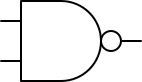
NAND and NOR
A NAND gate produces inverted output of an AND gate, just as if we sent the output of an AND gate to the input of a NOT gate.
| P | Q | AND (P \land Q) | NAND \neg(P \land Q) |
|---|---|---|---|
| 0 | 0 | 0 | 1 |
| 0 | 1 | 0 | 1 |
| 1 | 0 | 0 | 1 |
| 1 | 1 | 1 | 0 |
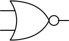
A NOR gate produces the inverted output of an OR gate.
| P | Q | OR (P \land Q) | NOR \neg(P \lor Q) |
|---|---|---|---|
| 0 | 0 | 0 | 1 |
| 0 | 1 | 1 | 0 |
| 1 | 0 | 1 | 0 |
| 1 | 1 | 1 | 0 |
These have their own symbols. Here’s a NAND gate:
and here’s a NOR gate:
NAND and NOR are universal logic gates, that is, we can construct any logic circuit we like, to perform any possible logical operation using only NAND gates or only NOR gates.
XOR, the exclusive OR
The XOR (exclusive OR) gate produces an output of 1 only when its two inputs differ. In Boolean algebra, this can be expressed as Y = P \oplus Q. If either P or Q is true, but not both, the output will be 1. However, if P and Q are both true, the output will be 0. This is why we call this “exclusive or.”
Here is a truth table for XOR:
| P | Q | XOR (P \oplus Q) |
|---|---|---|
| 0 | 0 | 0 |
| 0 | 1 | 1 |
| 1 | 0 | 1 |
| 1 | 1 | 0 |

Combinational Logic
Now that we understand these basic gates, we can use these to construct combinational circuits. A combinational circuit is a connected collection of logic gates whose operations depend solely on their immediate inputs (without any dependence on past inputs or memory). There a great many combinational circuits. Among these are multiplexers, decoders and encoders, and adders.
© 2025 Clayton Cafiero.
No generative AI was used in writing this material. This was written the old-fashioned way.