Logic gates

We’ve seen how to construct a fast, robust inverter—a NOT gate—with CMOS design, one NMOS and one PMOS. We’ve also seen how to construct a NOR gate (not AND) with two NMOS and two PMOS.
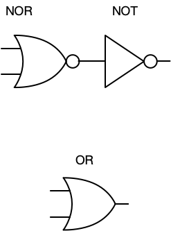
There are many different kinds of logic gates. The AND, OR are two obvious ones and you are likely familiar with the truth tables for the operations these implement. There are other kinds of gates as well, including NAND (NOT AND), NOR (NOT OR, which we’ve already seen), XOR (exclusive OR), etc. We’ve seen how to construct an OR gate by chaining a NOR and a NOT.
Recall that truth tables for NOR and NOT look like this:
| P | \neg P |
|---|---|
| T | F |
| F | T |
| P | Q | \neg (P \lor Q) |
|---|---|---|
| T | T | F |
| T | F | F |
| F | T | F |
| F | F | T |
We’ve already completed CMOS constructions of these gates, and we can construct an OR gate with a NOR and a NOT.
Now let’s see how to construct NOT, AND, and NAND using only NOR.
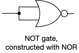
Notice that we send the same signal to both inputs of the NOR gate. This guarantees that the input is, in logic terms, either T and T, or F and F. If T and T, then the output of the NOR gate will be F. If F and F are the inputs, then the output of the NOR gate will be T. (Feel free to substitute 1 for T and 0 for F, if that works better for you.)
Now let’s see how we can construct AND from NOR.
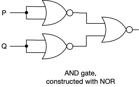
Remember we only want the output of this gate to be T if both inputs, P and Q, are T.
Input P is sent to both inputs of a NOR gate and this, as we have seen, functions as a NOT gate. Input Q is sent to both inputs of a NOR gate and, again, this functions as a NOT gate. So the output of the two NOR gates on the left will invert the signal. The output of each of these gates is sent to the input of a third NOR gate.
Let’s build a truth table for this
| P | Q | \neg P | \neg Q | \neg (\neg P \lor \neg Q) | P \land Q |
|---|---|---|---|---|---|
| T | T | F | F | T | T |
| T | F | F | T | F | F |
| F | T | T | F | F | F |
| F | F | T | T | F | F |
So this construction does indeed compute P AND Q, which is equivalent to NOT (NOT P OR NOT Q).
To construct a NAND, we just add a NOT gate to the output.
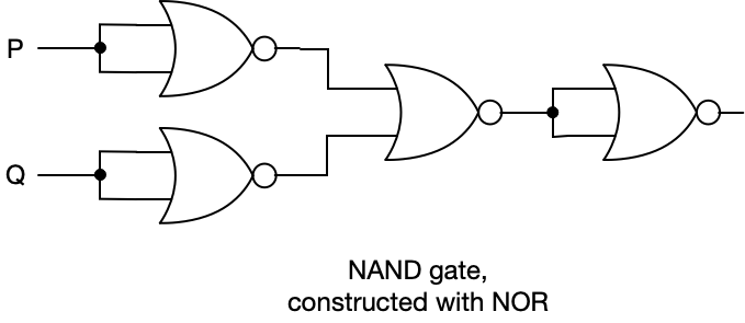
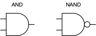
AND and NAND have their own symbols:
Exercises
Construct an OR gate using only NAND gates.
Construct a NOR gate using only NAND gates.
Universal logic gates
We’ve seen how to construct a number of gates using only NOR, and we can do the same thing with only NAND. For this reason, we call NOR and NAND “universal logic gates” because we can construct gates or circuits to perform any logical operation whatsoever using only NOR or only NAND. This is a very powerful idea. The idea actually dates back to the late 1800s in the work of logician and philosopher Charles Sanders Peirce. Peirce wasn’t concerned with hardware and transistors were a long way off, but he developed the original foundations for these kinds of constructions.
Now that we’re armed with universal logic gates we can construct other circuits to do many things!
© 2025 Clayton Cafiero.
No generative AI was used in writing this material. This was written the old-fashioned way.