Fetch, decode, execute (repeat!)
At its core, the operation of every computer is governed by process known as the fetch–decode–execute cycle, sometimes simply called the instruction cycle. Regardless of the complexity of modern hardware, this cycle remains the heartbeat of the CPU, the rhythm by which all programs run. At root, it’s a loop: fetch an instruction, decode an instruction, execute the decoded instruction, repeat!
Let’s start with a little terminology:
- an instruction is what tells the computer what to do (e.g., add two numbers), and
- registers are small memory locations that a CPU or ALU uses to hold operands, results of computations, memory addresses, and so on, and
- the clock, is a device which emits pulses of a fixed very precise frequency, which are used to regulate the fetch-decode-execute cycle.
Fetch
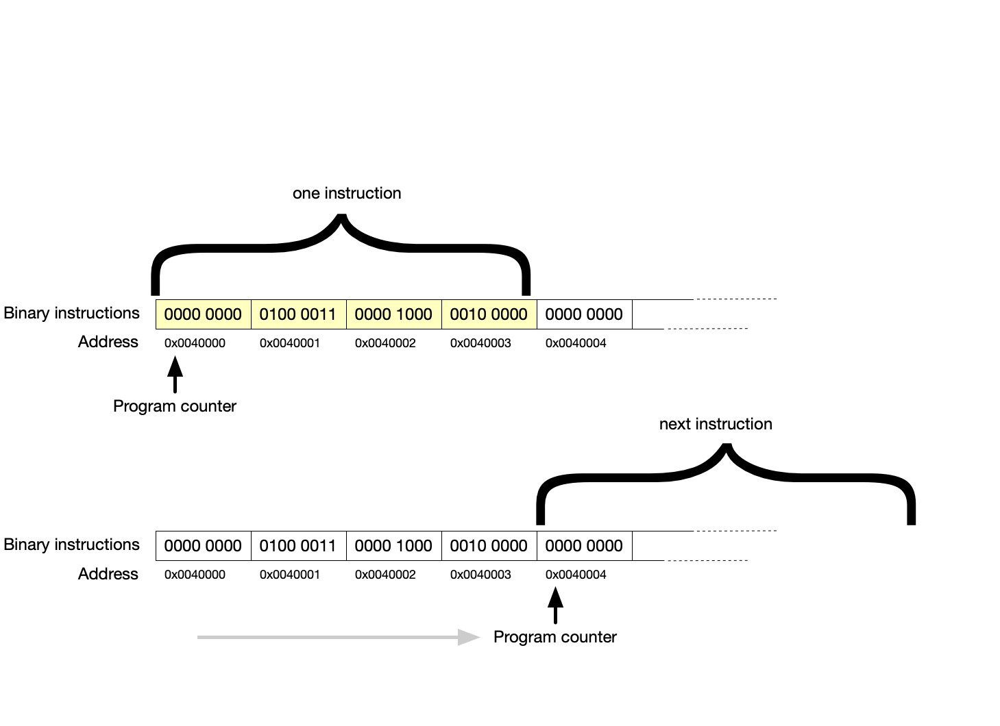
The first step is to fetch the next instruction from memory. The CPU maintains a special register called the program counter (PC), which holds the memory address of the next instruction to be executed. The control unit sends this address over the address bus to main memory, which then returns the instruction’s binary code over the data bus. The instruction is placed into another register, often called the instruction register (IR), where it can be decoded in the next step.
Once the instruction is fetched, the program counter is usually incremented so that it points to the next instruction in memory. In the simplest case, instructions are stored sequentially, so adding the length of one instruction to the PC will point to the correct location for the next instruction. However, not all instructions follow sequential flow—control instructions such as branches, jumps, or function calls may change the PC to point to a different location, allowing the program to alter its path of execution.
Example
Suppose the program counter on a MIPS machine’s program counter currently holds the address 0x00400000—the memory address of the current instruction (MIPS is an important RISC architecture). The CPU fetches the instruction at this location—for example, an ADD R1, R2, R3 instruction. The PC is then incremented to 0x00400004 to prepare for the next instruction, assuming a 32-bit instruction size. Here, the program counter is incremented by four, assuming a fixed instruction size of 32-bits, which is four bytes.
Note that the instruction size and the word size needn’t be the same.
A word is the natural unit of data the CPU operates on in registers and ALU operations. In a 32-bit architecture, a word is usually 32 bits (4 bytes). In a 64-bit architecture, a word is usually 64 bits (8 bytes).
However, on MIPS 32, instruction size is 32 bits and word size is 32 bits, whereas on ARM 64 (AArch64), the instruction size is 32 bits (fixed), but the word size is 64 bits.
Decode
After the instruction has been fetched into the instruction register, the CPU must decode it to determine what action to perform. The binary pattern of the instruction is divided into fields, each of which has a specific meaning.
One part of the instruction is the opcode, or operation code, which specifies what operation is to be carried out. Other parts of the instruction may specify the source operands (registers or memory addresses to be read) and the destination operand (where the result will be stored).
Decoding is handled by the control unit, which translates the instruction’s binary fields into a set of control signals. These signals tell the datapath what to do: which registers to read, what operation the ALU should perform, whether memory should be accessed, and where the result should go.
Decode is the step that turns raw bits into what amounts to meaningful work orders for the CPU. Decode determines:
- which registers to read,
- what the ALU should do,
- whether to access memory, and
- which register (if any) to write back to, and
- indicating any flags might be set during execution.
Example
Looking at the illustration in the previous example, we see the instruction at the memory location indicated by the program counter is 0000 0000 0100 0011 0000 1000 0010 0000 (32 bits, grouped into 4-bit nibbles). This means (in assembly) ADD R1, R2, R3. The opcode specifies that this is an addition operation ADD. The first element R1 specifies where the result of the addition should be placed. The next two elements R2 and R3 indicate the registers which hold the two operands. So the instruction tells the ALU to add the values found in R2 and R3, and that the result should be written into R1. The control unit generates signals to fetch the values of R2 and R3, configure the ALU for addition, and prepare register R1 to receive the result… so everything at this point is ready to go, but we haven’t executed anything yet—that’s for execution.
Execute
The final stage is execution. The decode step has arranged everything so the CPU is ready to execute—all the CPU’s ducks are in a row, as they say. In the execute step, the CPU actually performs the operation specified by the instruction.
This may involve arithmetic in the ALU, accessing memory, or updating the program counter for a branch.
- For arithmetic and logical instructions, the ALU performs the operation on the input operands.
- For load or store instructions, the CPU interacts with memory: either reading data from memory into a register or writing data from a register into memory.
- For branch or jump instructions, the program counter is updated with a new address, changing the flow of execution.
The result of the instruction is then stored in the designated destination, typically a register or a memory location.
Example
Continuing the examples above, the ALU adds the values stored in R2 and R3. If R2 contains the number seven (0000 0000 0000 0111) and R3 contains the number five (0000 0000 0000 0101), the ALU produces twelve as a result (0000 0000 0000 1100). This result is written into register R1. At this point, the program counter has already been incremented, so the CPU is ready to fetch the next instruction.
Cycle Repeats
Once execution is complete, the cycle begins again: the CPU fetches the next instruction, decodes it, executes it, and so forth. This process continues for as long as the computer is powered on and running a program. Modern CPUs improve upon this basic model by overlapping multiple instructions (pipelining), executing instructions out of order, and using caches to speed up memory access. However, all of these optimizations are still based on the same fundamental fetch–decode–execute cycle.
Importance
Understanding the fetch–decode–execute cycle is key to understanding how software interacts with hardware. Every program you write in a high-level language is eventually broken down into instructions that pass through this cycle. From running a simple calculator application to rendering 3D graphics, the CPU is always fetching, decoding, and executing billions of instructions per second.
Check in
If a CPU is fetching, decoding, and executing billions of instructions per second, what are the likely units for clock speed?
Adapted from "Patterson and Hennessy, Computer Organization, ARM edition" by Surya Malik and Clayton Cafiero.
No generative AI was used in writing this material. This was written the old-fashioned way.