
New: Download Schematic/Pictoral/Block Diagrams.
Bearcat 210 Block Diagram
Bearcat 210 Pictoral Diagram
Bearcat 210 Schematic Diagram
BC 210 Owners Manual(Pdf)Modifications to the 210 will provide the following:1) Reception of 137 MHz Range. 2) Increased bandwidth of the IF. 3) Low Level audio outputModification to the Bearcat 210 scanner for reception of 137 MHz FM is a fairly simple process. These receivers operate from 146 to 170 MHz using low side oscillator injection, with a non-standard (10.8) MHz Intermediate Frequency. By utilizing High side injection with the oscillator above the input frequency we can receive 137MHz simply by selecting a frequency 21.6 MHz above 137.xx MHz. Examples below are frequencies for NOAA and METEOR satellites.BC210 Weather Sat Freqs (F+21.6)
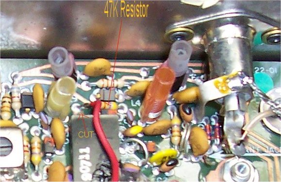
Channel Scanner Freq Satellite Sat Freq 1 158.9 MET 2-17 137.3 (137.3+21.6=158.9) 2 159.1 NOAA 10 137.5 2 159.1 NOAA 12 137.5 3 159.22 NOAA 14 137.62 3 159.22 NOAA 11 137.62 4 159.45 MET 2-20 137.85 4 159.45 MET 3-5 137.85Of course the rf amplifier is now tuned to 158 MHz and needs to be re-tuned to 137 MHz. The Bearcat receiver design utilizes "track-tuning" using varactor diodes on the rf amplifier stages. At 158 MHz the Voltage on the diodes is approximately 9 V. At 137 MHz the voltage needs to be about 3 V. This voltage isn't critical since the Rf stages are fairly broad. Make a simple voltage divider using a 100K pot in series with a 10K resistor connected to the internal 10 V power Supply. The CT of the pot is tied to the control diodes after cutting the circuit land on the circuit board going to the VCO Tuning Voltage. Where to cut the circuit land and install the CT wire? Look at the component side of the circuit board near the Antenna input to the scanner. Locate Coil labeled L9. Just to the right of this label is a 47 K ohm Resistor connected to a land connection with two traces. The CT of the pot issoldered to the resistor at the land. The trace going to the IC is cut. The 10 V can be obtained from regulator Q8.If your board is not labeled with component numbers you can identify Coil L9 as follows:__ Ext. Blue->O Blue->O I__I Antenna * L9 YELLOW-->O Red->O Input L9 47 Kohm 10K 100K POT O /-0--/\/\/\/\- 10 V 0-\/\/\/--/\/\/\/-Gnd / |^\Cut ^CT------------/ | \ TO ICThe Receiver is now modified for tuning the 137 MHz range. The receiver should be sensitive enough to hear satellites once the pot is adjusted to 3V. Once a satellite is heard, fine tuning of the pot for the strongest signal is recommended, however stay as close to 3 V as possible to detune the Rf amps away from the 158-159 MHz range. The IF on the scanner is +/-5 kHz for Narrow band FM reception .This will give marginal APT pictures.
To increase the bandwidth to +/-20 kHz, 1 of the two 10.8 MHz filters (FL1 or FL2)must be removed and replaced with a jumper. Narrow bandwidth was achieved using 2 filters in series. This crystal filter is located between Y1 and Y2 next to R3 labeled on the board. Cut the traces going to the filter and install a jumper in place of the filter. The filter can be left in place soldered to the board. Note: I removed both filters from the circuit board and remountedone filter to the foil side of the board. This is an alternative but not necessary. This completes the conversion to the scanner.
The scanner should have a GASFET preamp installed in order to get "state of the art" low noise figure performance. I am using a Hamtronics $29 preamp with excellent results. I use a linearly polarized 7 Element 2 Mtr Beam AZ/EL and get noise free APT pictures with the satellites 2-4 degrees above the horizon. The only possible problem that will be encountered is reception of commercial signals on the 158-159 MHz frequencies since the receiver is tuned to the image freq. I am using a military filter at the antenna input to attenuate the 1 local signal I have on NOAA 9 (159.22) freq. This is a F-193/U Army Bandpass filter with a frequency range of 121-142 MHz which i found at a hamfest.
Low level audio output can be obtained by soldering a wire to the high side of the volume control. This wire can be brought out to a phono connector on the back panel. This will allow constant audio amplitude to the demodulator board . I am using the MultiFAX demodulator that has its own level control.
I would like to acknowledge the "Weather Satellite Handbook"by Taggart for the ideas in this conversion. Have fun and good APT reception.
ReturnS. Warley's Home Page